Rewiring the Anti Lock Brake (ABS) – we hope final edition!
This update covers ABS rewiring on Factory Five Roadster #9772. The antilock system has been a long challenge. In fact, I have no less than eight posts about the ABS setup.
Related notes live on the Factory Five Cobra build hub. Earlier planning is in GT500 ABS Planning.
ABS rewiring: hardware on this car
First, here is a quick recap of the brake and ABS configuration.
- Whitby Motorcars Power Brake Kit. Had I started over, I would have used hydroboost. Still, that choice is behind me now.
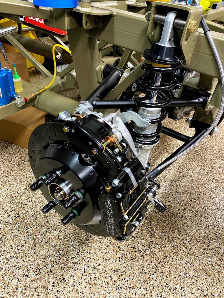
- 12.88″ front and 12.19″ rear Wilwood brake kit from the 25th Anniversary Kit
- Electronic Parking Brake Rear Retrofit Brake Kit
- 2007-09 Mustang GT500 Hydraulic Control Unit (HCU)
Research that locked the wiring plan
After hours of research across several sites, I believe the wiring setup is finalized. These threads helped the most:
- trackmustangsonline.com
- community.drivenasa.com (Ford Racing ABS install)
- johngeorgeracing.com — prior owner of FFR #48 Type 65
- community.drivenasa.com (FR500S ABS)
GT500 ABS module diagrams
Next, start with the GT500 setup diagrams and pinouts.
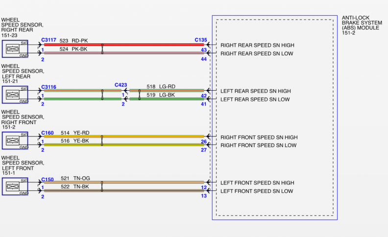
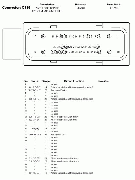
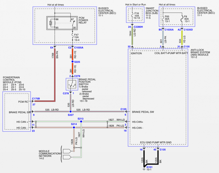
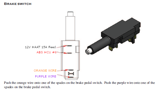
How we wired ABS module 151-2
The primary ABS module in the diagram above is 151-2. Here is how we wired it.
- Brake pedal switch #6 from the HCU goes to one rear spade on the FFR brake switch. That circuit is normally closed. It opens when depressed. Front spades power the brake lights instead. The other side of the switch is a 15A fused HAAT feed. See the pic above.
- HCU ports #16 and #45 go to ground. We ran those direct to the battery post.
- HCU port #32 runs to the new fuse panel Key-On/Run circuit with a 10A fuse.
- HCU #2 needs a 30A HAAT feed. HCU #31 needs a 40A HAAT feed. See the pic below.
- HCU #3 is HS-CAN+. HCU #18 is HS-CAN-. Those use a 120 Ohm resistor and run back to their own OBD2 port.
Dedicated ABS OBD2 port
Finally, here is the OBD2 port configured only for ABS. It is separate from the Coyote OBD2.